Industrial Stepper Motor Controller Board
EBabutzky GmbH (Germany)
STM32F4-based precision motion-control board for EBabutzky GmbH (Germany) — stepper/H-bridge drive with closed-loop PID and encoder feedback, controllable over Modbus RTU/TCP. Evolved from a single-MCU design into a distributed dual-MCU architecture for safety and precision.
Overview
Client: EBabutzky GmbH (Germany)
Role: Lead Firmware Engineer — architecture, firmware design, and implementation
A precision motion-control platform built around the STM32F4 series for an industrial client in Germany specializing in precision engineering. The system drives stepper and H-bridge motor stages with closed-loop encoder feedback, and exposes full control and diagnostics over Modbus RTU and Modbus TCP for integration into existing industrial automation stacks (PLCs, SCADA, or custom master applications).
What makes this project a strong showcase of system-level engineering is its evolution: it started as a single-MCU design handling both communication and motor control, and was later re-architected into a distributed two-MCU platform — one MCU dedicated to communication, the other exclusively to motor control — with multiple boards subsequently built on this firmware to meet the client's safety and precision requirements.
Challenge
The client needed a motor controller that could:
- Support both stepper motor and H-bridge control modes from a single firmware platform
- Provide accurate closed-loop position control using encoder feedback and a configurable PID loop
- Be fully controllable and diagnosable over industrial fieldbus protocols (Modbus RTU and TCP)
- Support external stepper drivers (e.g. DM542T) with configurable microstepping and pulses-per-revolution
- Communicate over Ethernet (via W5500) and RS-485 simultaneously for flexible deployment
- Scale to a safety- and precision-critical production environment, where timing jitter or a communication-side fault could not be allowed to affect motor control
That last requirement is what drove the architecture beyond a single-MCU solution.
Approach
System evolution: from single MCU to distributed architecture
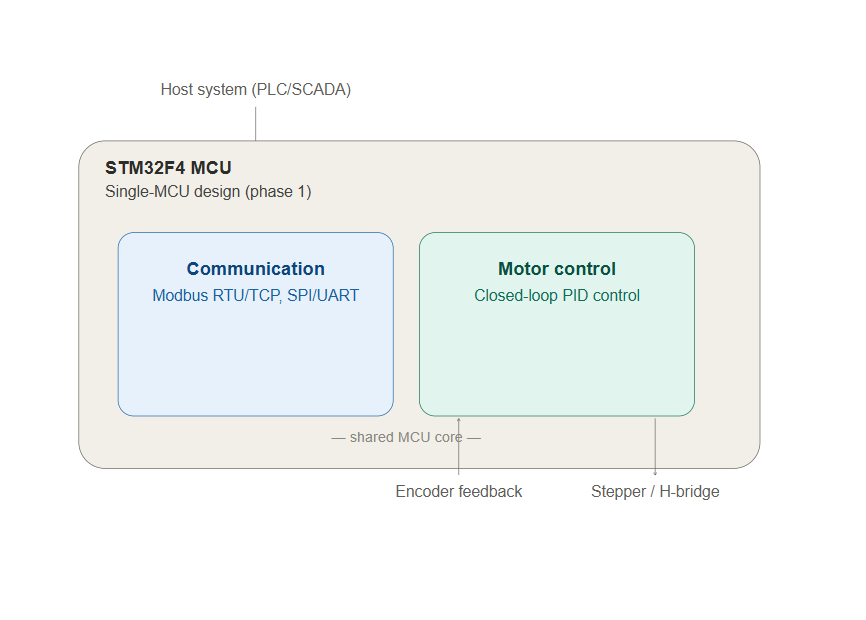
Phase 1 — Single-MCU design. The initial implementation used one STM32F4 MCU to handle everything: Modbus RTU/TCP communication (via SPI to a W5500 Ethernet controller and UART for RS-485), motor control (stepper/H-bridge), encoder feedback, and the PID control loop. This proved the concept end-to-end and validated the register map, control logic, and communication stack on real hardware.
Phase 2 — Split into two dedicated MCUs. As the project matured toward production, the client's safety and precision requirements made a single shared MCU a liability: a communication-side hiccup (a malformed Modbus frame, a network stall, a flash write) on the same core as the real-time motor-control loop introduces exactly the kind of timing non-determinism precision motion control can't tolerate. The firmware was re-architected into two cooperating STM32F4 MCUs:
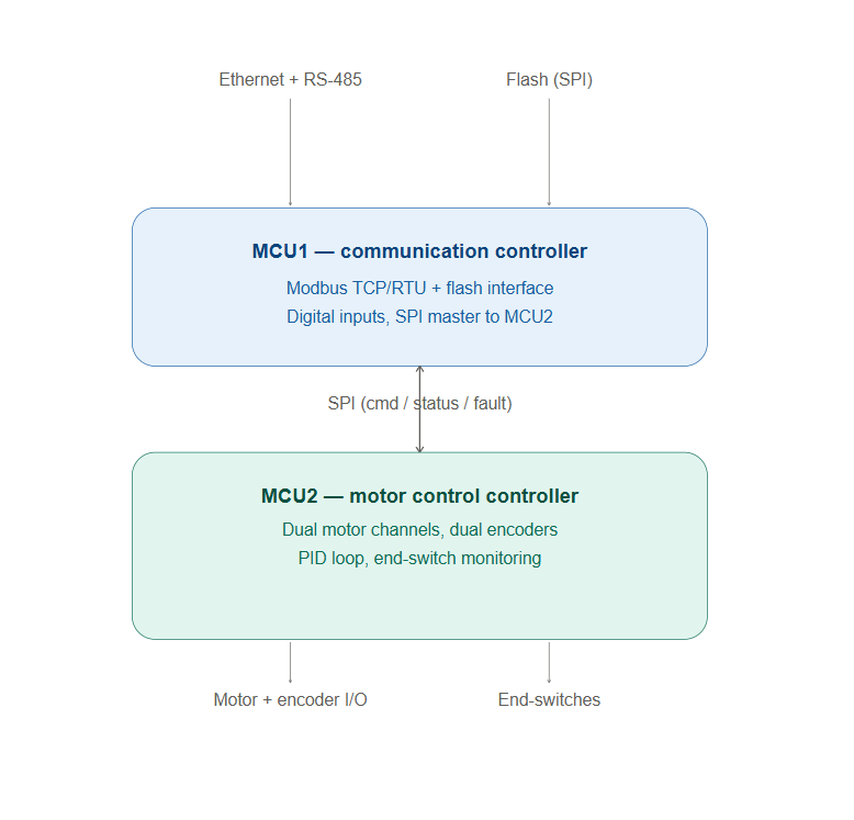
- MCU1 — Communication controller: owns the Flash SPI interface, the Ethernet SPI link to the W5500 (Modbus TCP), RS-485 (Modbus RTU), and digital inputs. It absorbs all the non-deterministic, I/O-bound work — parsing frames, managing the network stack, handling flash access — without ever touching the motor-control timing path.
- MCU2 — Motor-control controller: owns the real-time-critical work exclusively — driving two independent motor channels, reading two quadrature encoders (with index), monitoring end-switches, and running the PID loop — isolated from communication jitter entirely.
- Inter-MCU link: the two MCUs are tied together over a dedicated SPI link (MCU2 as SPI slave to MCU1), carrying commands and status between the communication and control layers, plus a fault-reporting path so MCU2 can flag a motor fault upward without waiting on a Modbus poll cycle.
This separation of concerns — communication logic and control logic on physically separate processors, connected by a narrow, well-defined interface — is a standard pattern in safety-oriented industrial motion control, and multiple production boards have since been built on this two-MCU firmware architecture.
Technical approach
- MCU1 (communication): SPI-based Flash access, SPI-based Ethernet (W5500) for Modbus TCP, UART/RS-485 for Modbus RTU, digital-input handling, and the SPI master link to MCU2.
- MCU2 (motor control): dual independent motor channels (stepper and/or H-bridge), dual quadrature encoder inputs with index channels, end-switch monitoring, and the PID control loop — running as an SPI slave to MCU1.
- Motor-control layer: configurable per channel for stepper or H-bridge operation, driving external hardware such as a DM542T stepper driver with configurable microstepping and pulses-per-revolution.
- Closed-loop feedback: quadrature encoder input feeds a PID controller with independently tunable Kp/Ki/Kd, configurable setpoint, and integral-output clamping to prevent windup.
- Modbus register map: a single, consistent register map spanning Coils, Discrete Inputs, Input Registers, and Holding Registers — encoder position/direction/resolution, stepper step angle and RPM, motor enable/fault/clear-fault, and full PID tuning — exposed identically over both RTU and TCP by MCU1, regardless of which MCU internally owns the data.
Design decisions worth noting
- Communication first, control second. In the single-MCU build, the SPI/Ethernet path was implemented and validated on real hardware before layering in motor control, reducing late-stage integration risk.
- Splitting for determinism, not just modularity. The move to two MCUs was a direct response to a safety/precision requirement: keeping the real-time loop on a processor that never shares cycles with network stacks or flash I/O.
- A narrow, well-defined inter-MCU interface. Rather than broad shared state, the SPI link carries a deliberately scoped command/status/fault protocol — keeping the two firmware images loosely coupled and independently testable.
- Single register map, dual transport, dual MCU. Both Modbus transports and both MCUs present the same logical register set outward, so the client's SCADA/PLC integration didn't change when the internal architecture did.
- Fixed-point-friendly register design. Position, step angle, and PID gains are transmitted as scaled integers rather than raw floats — keeping register widths predictable and avoiding endianness/format ambiguity across master implementations.
- Fault-aware motor control. Explicit fault / clear-fault registers, with a dedicated fault path from MCU2 to MCU1, let a supervising PLC/SCADA detect and clear faults promptly rather than waiting on a poll cycle.
Key features
| Subsystem | Capability |
|---|---|
| Architecture | Distributed dual-MCU design: dedicated communication MCU + dedicated motor-control MCU, linked via SPI |
| Encoder | Dual-channel position, direction, resolution, PPR, and raw count over Modbus |
| Stepper control | Step angle, max RPM, steps/revolution, DM542T microstepping, dual independent motor channels |
| Motor controller | Stepper/H-bridge mode select, enable, fault detection & clear, position in % and degrees |
| PID loop | Full closed-loop tuning (Kp/Ki/Kd, setpoint, integral clamp) via Modbus |
| Connectivity | Simultaneous Modbus RTU (RS-485) and Modbus TCP (Ethernet via W5500) |
| Safety | Communication and real-time control isolated on separate MCUs to eliminate cross-talk jitter |
Results
Status
The single-MCU firmware was implemented and hardware-validated first. The architecture was then split into the two-MCU design described above, and multiple production boards have been built around this firmware for improved safety and precision. Ongoing work focuses on finalizing the inter-MCU protocol details and completing full integration testing across the fleet of boards.
Why it matters
This is a clean example of letting a hard requirement drive architecture: a precision- and safety-critical motion controller where communication jitter simply cannot be allowed to reach the control loop. Moving communication and real-time control onto physically separate STM32F4 processors — joined by a narrow, well-defined SPI interface, behind a single Modbus register map — is the pattern industrial motion-control and automation teams reach for, delivered here for a German precision-engineering client and now carried across a fleet of production boards.
Gallery

.jpeg)
.jpeg)
104 views