Magnetic Hall-Effect Keypad Gamepad — Hardware & Firmware
Japanese gaming hardware client
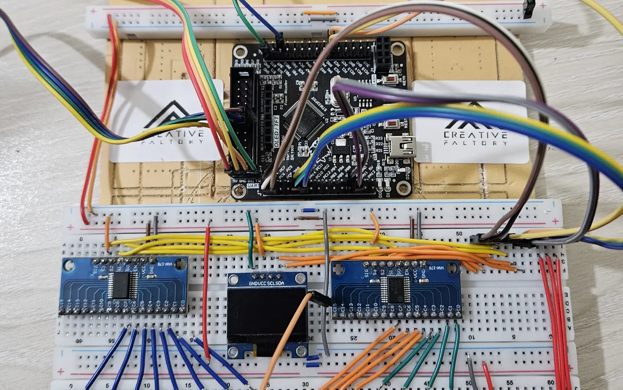
Hardware design and firmware for a magnetic keypad gamepad: 16 analog Hall-effect keys read through two multiplexers by DMA-driven ADC sampling on an STM32F407, with an OLED and rotary-encoder settings menu and USB to the PC.
01
Context
A mid-range commercial gamepad for a Japanese gaming hardware client, delivered in 2024. Its keys are analog and magnetic: each one has a Hall-effect sensor that measures how far the key is pressed, so the point at which a key acts, and how sensitive it is, can be set on the device instead of being fixed by a mechanical switch.
02
Challenge
Reading many analog magnetic keys fast and reliably.
- Sixteen analog keys, read without pause. Each key is a Hall-effect sensor, so the firmware reads levels rather than on/off contacts, and has to keep reading all of them.
- Low latency. A press has to register as soon as the key crosses its actuation point, whatever else the firmware is doing.
- Shared ADC inputs. The sensors reach the microcontroller's ADC through two analog multiplexers, so channel switching and sampling have to stay in step, with no key missed or mixed up.
- Settings without a PC. Users adjust the actuation point and sensitivity on the device itself.
03
Approach
Signal chain
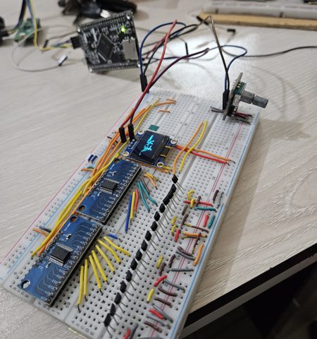
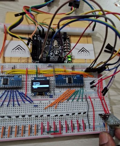
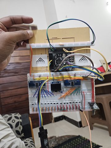
The 16 Hall-effect sensors feed two analog multiplexers, and the multiplexer outputs go to the ADC channels of an STM32F407.
DMA-driven ADC sampling
The ADC samples at a high rate and DMA moves every conversion straight into memory, so key scanning runs continuously in the background, with low latency, and the CPU stays free for the rest of the firmware.
On-device settings
An OLED display and a rotary encoder give the gamepad its own menu, for settings such as the actuation point and sensitivity.
USB, and a tool for testing
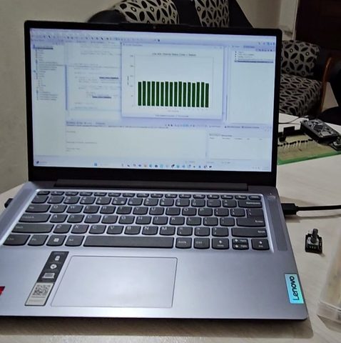
The gamepad connects to the host PC over USB. A UART link feeds a Python GUI tool that shows the live reading of every sensor, for testing and calibration.
My part
- Hardware design: the system architecture and the schematic-level design, including the sensor, multiplexer and ADC signal chain
- All of the firmware: ADC and DMA scanning, multiplexer control, USB, the OLED menu and rotary encoder, and the UART link to the test tool
- Not my part: the PCB layout, which was done by others
04
Stack
05
Result
Delivered to the client, and taken into production at the client's site.
“very knowledgeable, and willing to do hands-on troubleshooting together.”
Gallery